The descriptions of the various interfaces of the industrial control all-in-one computer are as follows.
Product knowledge 2026-02-06
The descriptions of the various interfaces of the industrial control all-in-one computer are as follows.
- Display interface: The display interface typically has four types of interfaces:
The most common type is VGA. The machine comes with its own interface. When customers purchase industrial displays, they will receive VGA cables. Simply insert them into the interface and the output will be analog signals. The pin count is 15. Using the video interface of VGA is equivalent to going through a digital-to-analog conversion and an analog-to-digital conversion. There is signal loss and the display is relatively blurry. - DVI-I (can be converted to VGA), DVI-D, there are two standards for DVI interfaces, 25-pin and 29-pin. The DVI interface transmits digital signals and can transmit high-resolution video signals. When connecting the computer graphics card and the display through DVI, no conversion is required, so there is no signal loss.
- HDMI interface. The HDMI interface also transmits digital signals, so the video quality is basically the same as that achieved by the DVI interface. The HDMI interface can also transmit audio signals. Therefore, the transmitted content is high-definition video.
- DP interface, DisplayPort (abbreviated as DP); DisplayPort is the first display communication port that relies on data packetized data transmission technology. This data packetized transmission technology can be found in technologies such as Ethernet, USB and PCI Express. It can be used for internal display connections within industrial control hosts as well as external display connections.
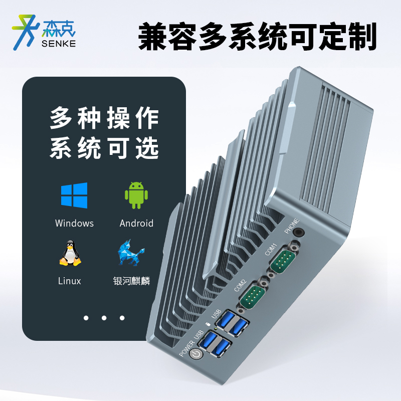
II. USB Interface of Industrial Control Computer:
- USB 2.0: White/Black interface;
USB 3.0/3.1: Blue interface;
USB 3.0 has a higher transmission speed than USB 2.0. USB 3.0 can be downward compatible with USB 2.0 devices, but the reverse is not possible. USB 3.1 is the current new USB transmission interface standard, with a transmission speed faster than USB 3.0 G. Our products are present on 8th generation motherboards. USB 3.1 can be downward compatible with USB 3.0 and USB 2.0 devices, but the reverse is not possible. The built-in encryption dongle USB is one that is added inside the machine. USB 2.0 adopts a 4-pin design, while USB 3.0 adopts a 9-pin design. Comparatively, USB 3.0 has more powerful functions.
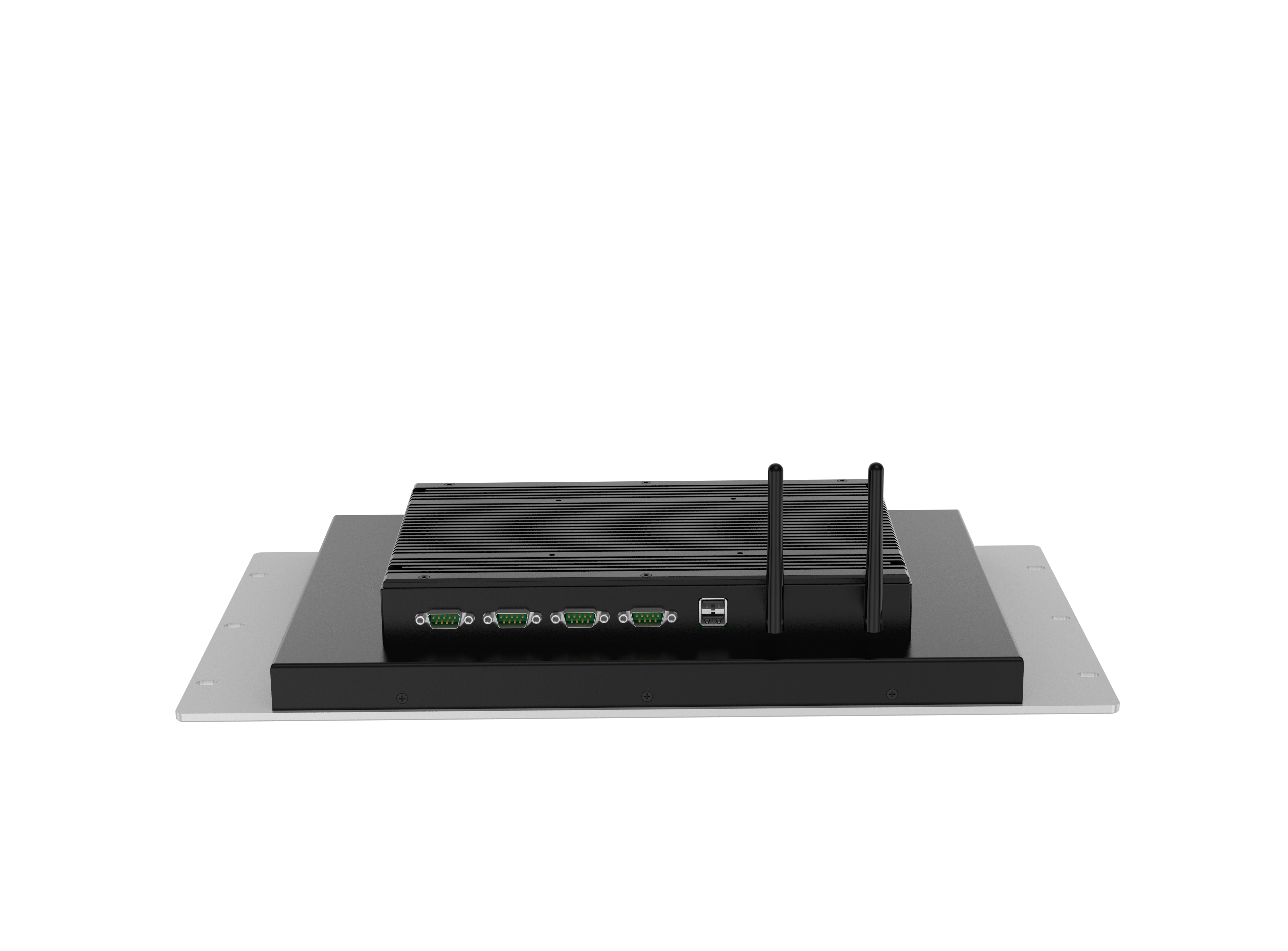
III. Industrial Control Computer Serial Ports:
They are divided into RS232/485/422. All are nine-pin connectors. The serial ports are determined by the customer’s needs. It is recommended to choose the appropriate one. Usually, COM3 and COM4 are 485 serial ports. RS232 uses unbalanced transmission and is called single-terminal communication. Due to the difference between the transmission level and the receiving level being only 2V to 3V, its common-mode suppression capability is very poor. Combined with the distributed capacitance on the twisted pair, the transmission distance is approximately 15m and the speed is 20kb/s. RS232 is point-to-point (that is, there is only one pair of closed devices) communication. The driving load is 3 to 7kΩ. Therefore, RS232 is suitable for communication between local devices.
RS485 was developed from RS-422, so RS-485 has many electrical requirements similar to RS-422. If balanced transmission is adopted, a termination resistor needs to be connected on the transmission line. RS-485 can be used for two lines and four lines. Two-wire system can achieve true multi-point bidirectional communication with four-wire connection, while RS-422 can only achieve point-to-multipoint communication, that is, a master control (Master) device, and the rest come from this device. However, it has been improved compared to RS-422. The four-wire or two-wire connection mode can receive up to 32 devices on the bus.
RS-485 and RS-422 are also different. The common-mode output voltages are also different. RS-485 has a range from 7V to +12V, while RS-422 has a range from 7V to +7V. The minimum input impedance of the RS-485 receiver is 12kΩ, and that of RS-422 is 4kΩ. Since RS-485 complies with all RS-422 specifications, the RS-485 driver can be used in the RS-422 network.